Hardware assembly | PiFactory and serial cable use | Rest of full setup for EnviroPHAT use | Jupyter notebook lowdown | Conclusion & links
Introduction
 The tiny version of the Raspberry Pi computer, the Pi Zero, is not much larger than a stick of gum yet is a full Linux-based computer (oh, and by the way it's only $5!). It's a bit less powerful than the larger Pi 2 & 3 models, but it uses much less power than they do allowing realistic battery implementation, while still being able to use the same "Hat" add-ons. So it's a potentially nice field sensor platform for some applications - and really quick and easy to get up and going. Here I experiment with a simple canned sensor HAT made by Pimoroni, the "Enviro pHAT", and running a Jupyter server on the Pi Zero to analyze/view the sensor data in a web-based Python notebook.
I bought these parts from Adafruit.com, a key business in these products. But note that wherever you buy them from, the Raspberry Pi company that makes these things is still small and not well-outfitted for mass production of this very popular computer, and stores still have a "you can only by one at a time" rule, which is kindof a pain. In a practical sense this means that instead of a $5 computer it ends up a $15 one, assuming you want to buy more than one (which you should since mistakes like putting jumpers/wires on the wrong pins can easily blow the thing out), because you buy one from each of several stores and add on a $10 or so shipping charge. In an even more practical sense, while the R-Pi0's are just $5 (or $15), note you'll need a handful of supporting gear to connect and use it. Often blogs talk of using HDMI cables to hook up to monitors, little USB hubs to hook up to keyboard and mouse, and an AC adapter to power from a wall plug, but you really don't need all that. You can easily get away with just the following, among which even the last two (batter and charger) are optional:
- Raspberry Pi Zero ($5),
- SD/MicroSD Memory Card (8 GB) ($10),
- Enviro pHAT by Pimoroni ($20),
- USB to TTL Serial Cable for Rasp. Pi ($10),
- Miniature WiFi (802.11b/g/n) Module ($12),
- USB cable - 6" A/MicroB ($3),
- USB OTG Host Cable - MicroB OTG male to A female ($3),
- Lithium Ion Battery - 3.7v 2000mAh ($13),
- PowerBoost 1000 Charger ($20).
Hardware assembly
 The first steps are soldering on the GPIO pin headers and copying the latest Rasperian distro of Linux (Jessie as of this writing) onto an 8GB microSD card; there are a million websites describing these (Google them!). The 40x2 header pin block comes unattached to the Pi, in case you wish a different config, but it's easy and forgiving to solder because its holes are far enough away from on-board heat-damageable components. Do make sure the microSD card is removed from the board when soldering. All the same is true for the EnviroPHAT too - but notice in the pictures that this one's soldering is done on the top as the header block is on the bottom to attach to the R-Pi's pins.
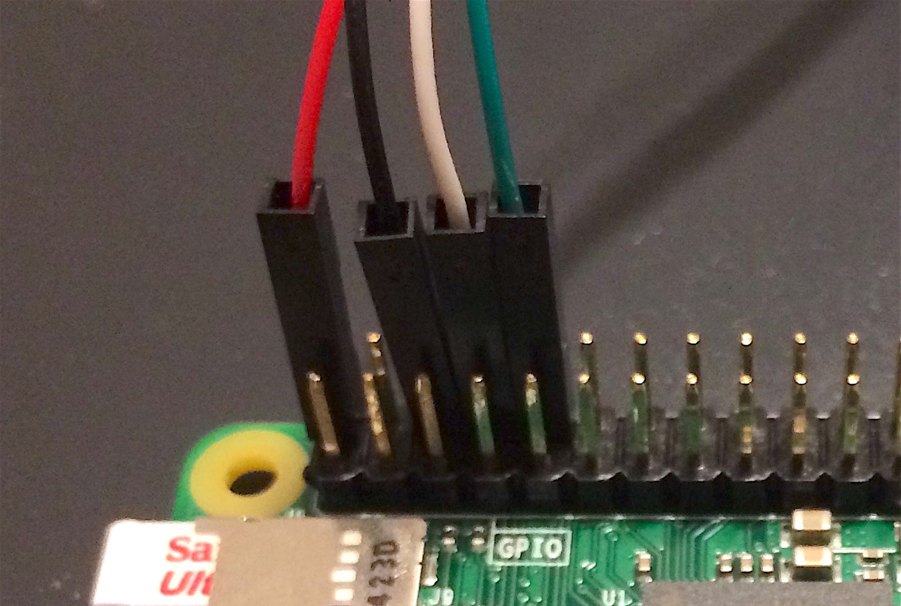
 Part a : serial connection. First let's just focus on the R-Pi, leaving the EnviroPHAT aside for a moment. As suggested above, you can Google up many how-to-solder-and-set-up-R-Pi websites, but an important note on them is that here we will focus entirely on the command-line-only version (Jessie Lite as of this writing), and we skip the HDMI, keyboard, mouse, and even standard USB power connection. The 4 serial wires provide power as well as a serial connection. The USB serial cable's wires are colored-coded for the particular pins they're meant for, as seen below. When things go perfectly, the ideal is that your new config on the microSD card including wifi login lets you simply SSH into the device the first time, no serial connection needed. But myself I find that things never go perfectly the first time, and the serial connection is an easy yet minimalist direct access into the device. You'll see below that after everything else is working I remove the serial wires, attach a battery, and do SSH in remotely, but one thing at a time.
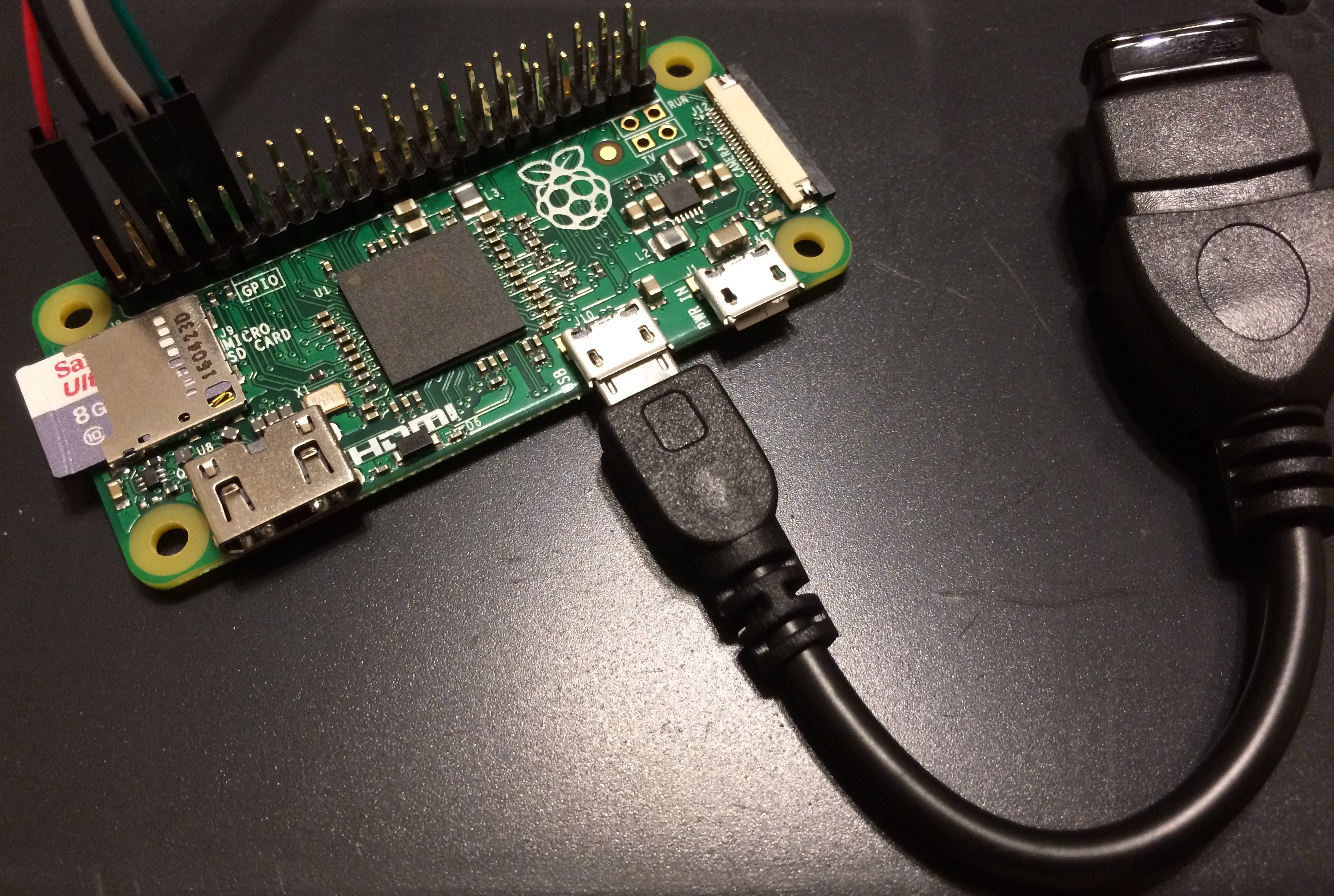
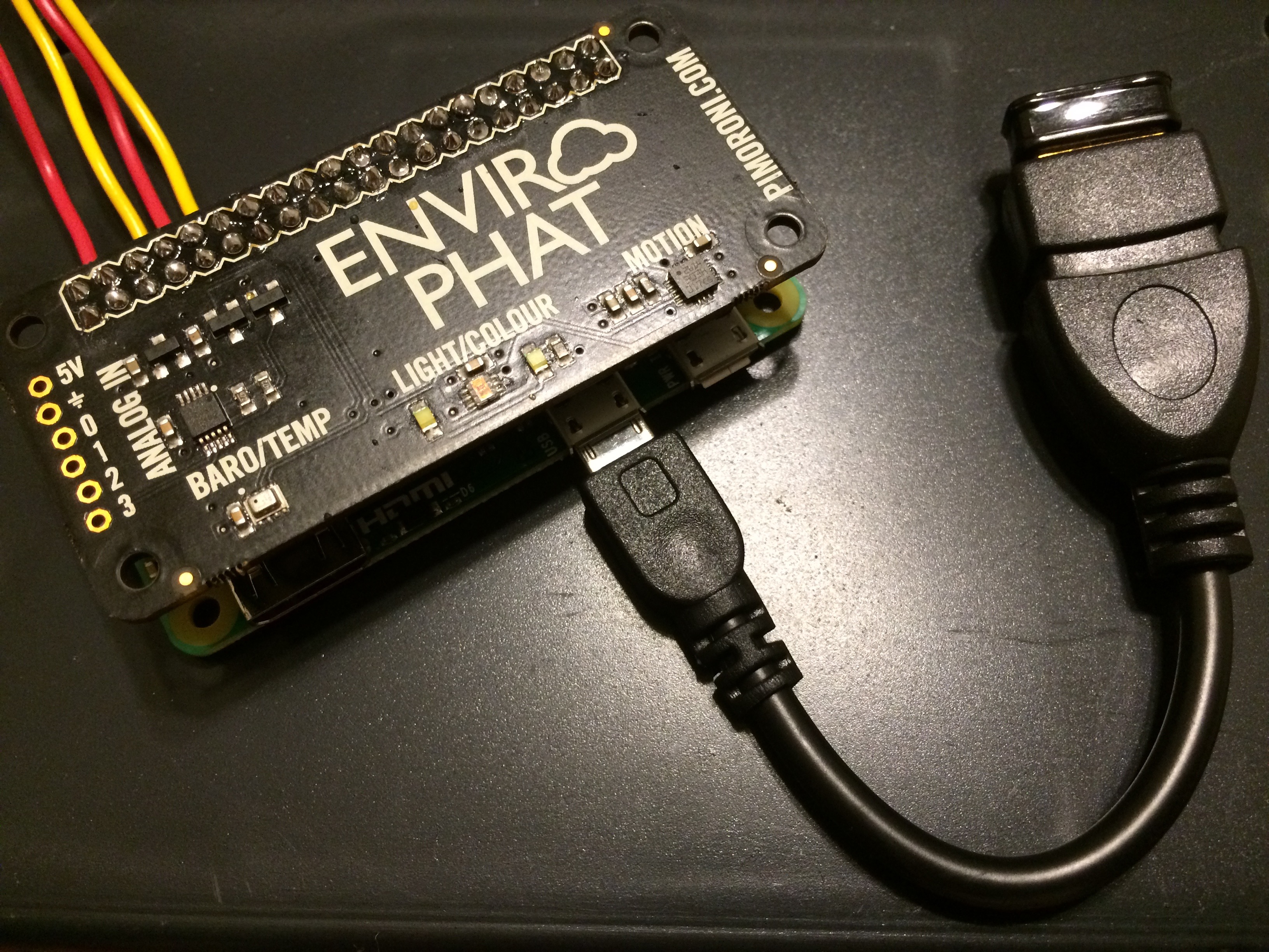
These first images show how/where I attached the USB wifi dongle and serial wires (the instructions come with the serial cable too). Red wire supplies the power (+5V), black is ground, white is serial XMIT, green is serial RCV. That skipped pin is another +5V pin. With these 4 serial wires attached, and the little wifi plug on the end of the USB dongle plugged in as in the picture, the unit is all ready for the PiFactory/system test described in part (a) of the next section. Remember the power comes via the red wire of the serial connection. No USB power necessary (in fact be sure to not do both at same time). I recommend trying out this much before attaching the rest of the hardware.
Part b : serial + EnviroPHAT. You may or may not wish to do this part and instead simply pop on the EnviroPHAT. In that ideal case, in part (a) one gets the wifi-based login working fine, and then attaches either AC adapter or battery to the USB power input, and does away with the serial connection. But for more experimentation, or perhaps to avoid the extra cost of AC adapter or the battery and charger/adapter unit, here's how I connected the serial wires at same time as the EnviroPHAT header.
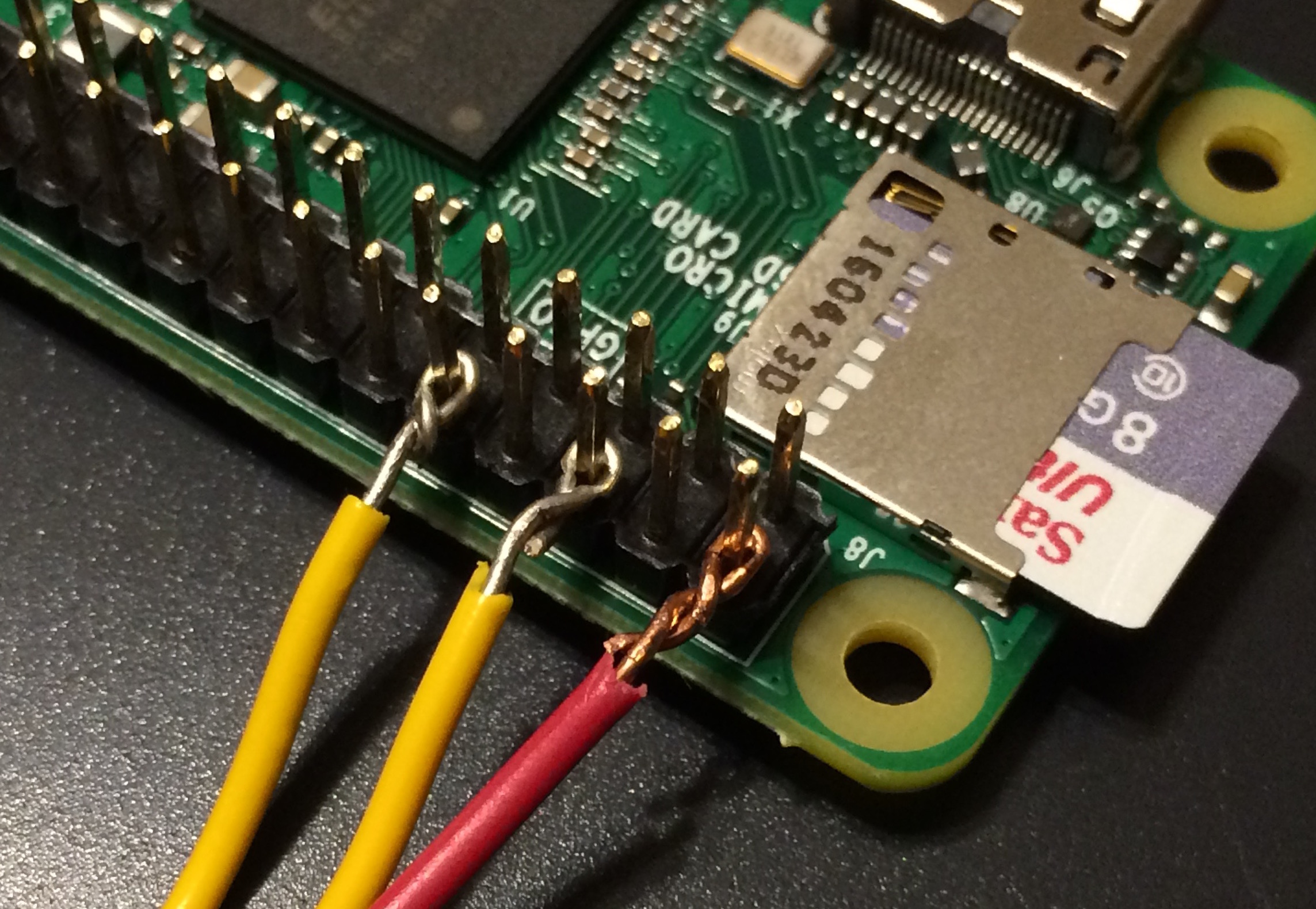
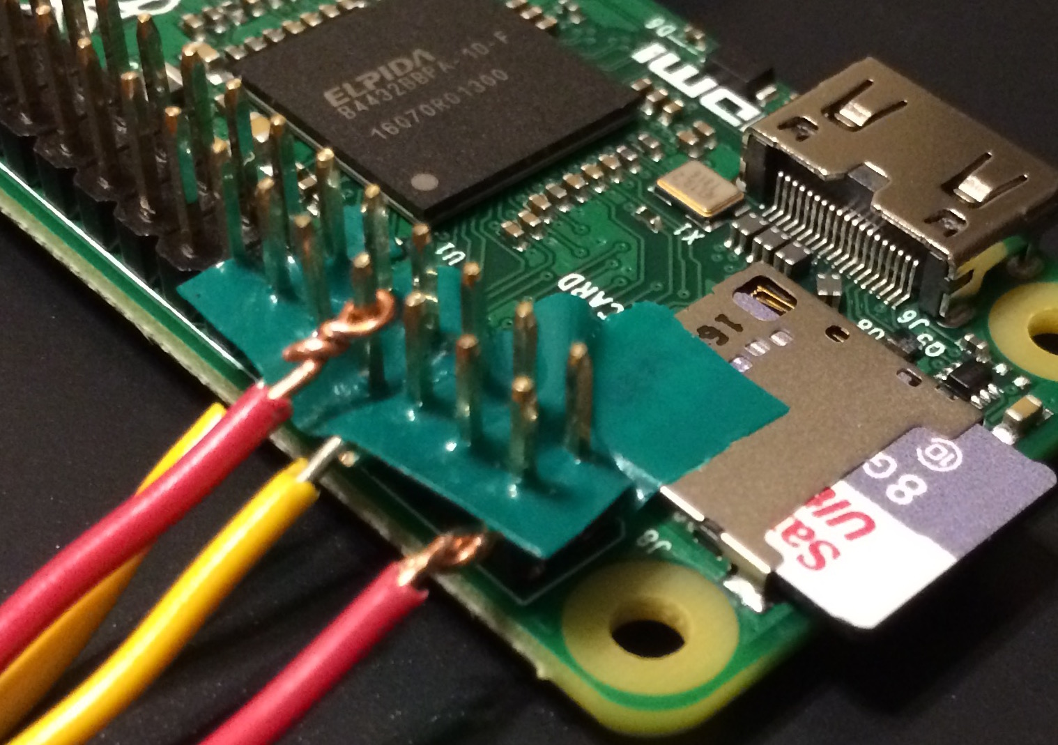
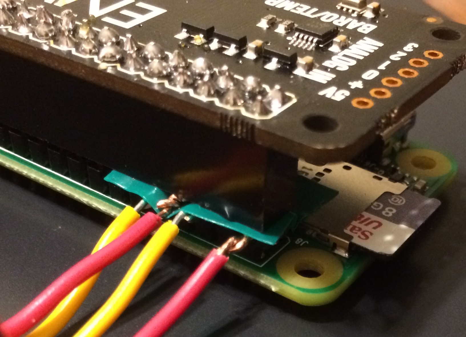
The key to connecting serial wires and EnviroPHAT at same time is that they don't use the same GPIO pins -- if they did they would interfere with each other and possibly blow out a component somewhere too. We can check via the EnviroPHAT's GPIO usage on its pinout.xyz page and see that EnviroPHAT doesn't use GPIO pins 2, 8, and 10 (or ground pin 6 which is just ground), which are the ones the serial wires are connected to. So I looped wires around those pins (with a tape separator for loops on neighboring pins so they don't touch), and these are held in place by the EnviroPHAT's header block. The white, black, red, and green serial cable leads connect to the wires leading to their pins - alas I didn't have black, white, red, and green wire handy during this quickie project so I just used red and yellow.
In this setup, we have the EnviroPHAT attached to the R-Pi, as well as the 4 serial cable wires (which include power), as well as the wifi USB dongle. Again you may wish to skip this step of attaching serial wires and EnviroPHAT at same time, and just rely on battery and wifi login after experimenting in part (a).
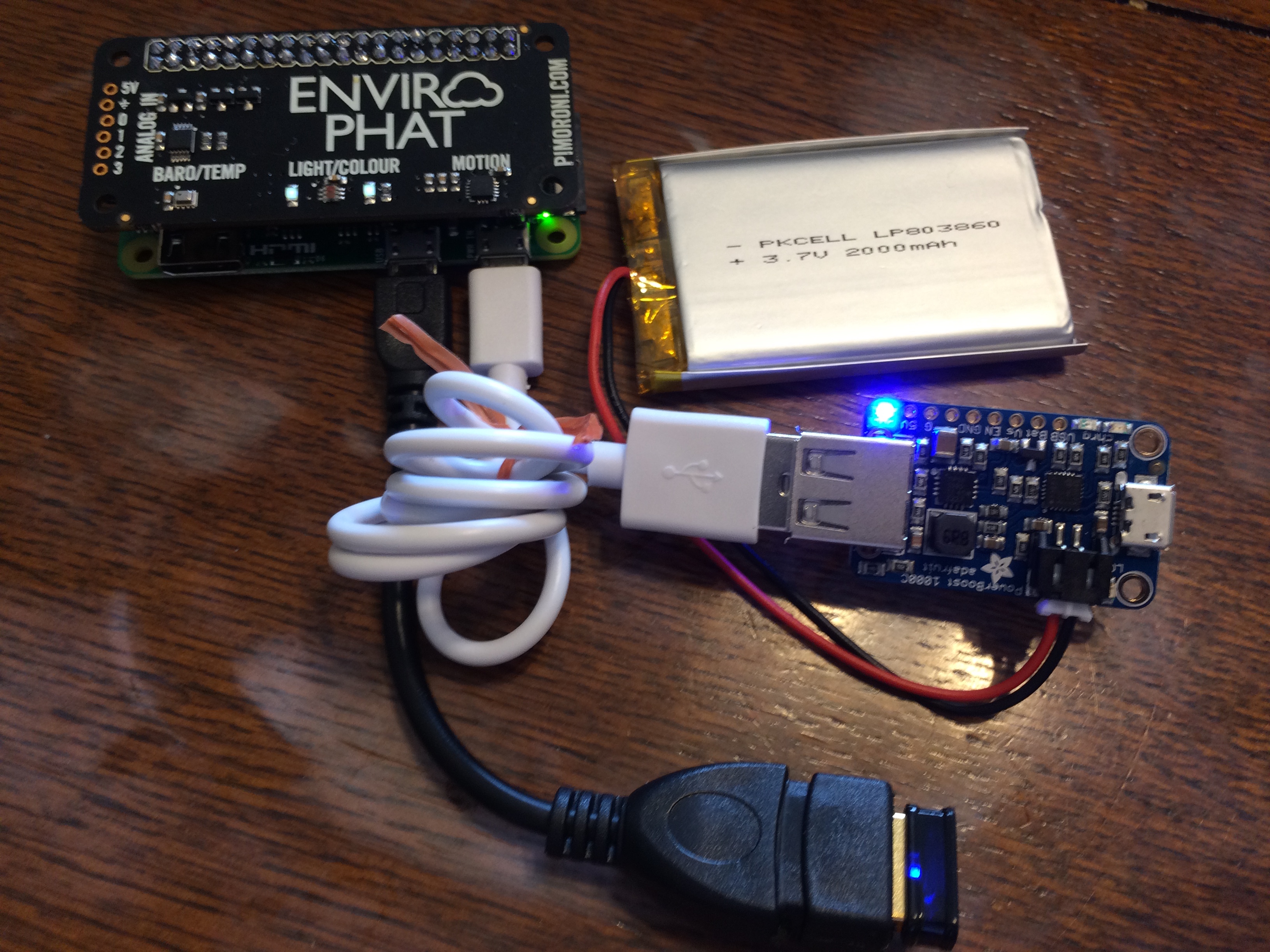
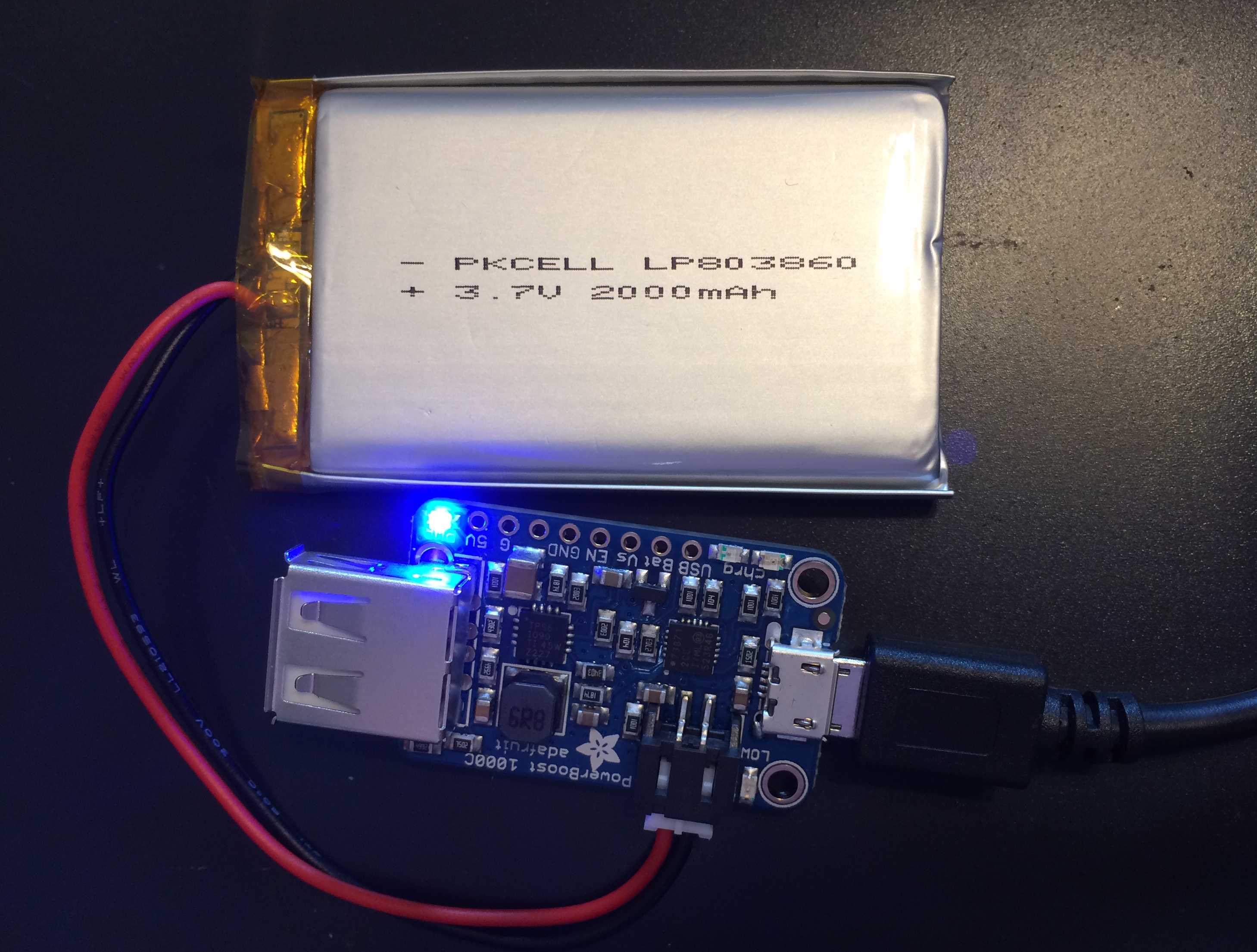
Part c : RPi + EnviroPHAT running on battery. Here's how I hooked up the battery, using the Powerboost 1000C. So far I've just used the white USB cable (coiled up there) to connect to the R-Pi's USB power input. But one can leave the full-size USB socket off the Powerboost, solder a pair of power wires from the Powerboost output directly onto the R-Pi's USB power input (the R-Pi actually has a pair of pads on the board for this), and mount the Powerboost underneath the R-Pi. In any case, what's really nice with the Powerboost 1000C is that you can charge the battery while still supplying power. So while the two pictures below show two separate configs of running-on-battery and recharging-the-battery-from-AC-adapter, really they can be done at the same time. Note that blue light on the Powerboost turns red when you reach low battery. When charging it was yellow until charged up when it was blue again. This webpage shows a nice setup for a Powerboost mounted under the R-Pi to run a low-battery line to a GPIO pin for software alert but I haven't tried it myself yet.
